



요꼬가와는 1915년 창립이래 계측, 제어, 정보기술을 축으로
최첨단의 제품을 산업계에 제공함으로써 사회 발전에 공헌해오고 있습니다.
산업별 어플리케이션
대형 풍력 발전 전류용 고정밀 전류 센서

 대형 풍력 발전 전류용 고정밀 전류 센서.pdf (1.3 MB)


1. 서론
전 지구적 환경 문제에 대한 대응책으로 재생에너지 분야에 풍력 발전 시스템이 도입되고 있습니다. 이러한 시스템은 발전기 모터에서 생산된 전력을 전력망에 연결하여 전기를 공급합니다. 풍력 발전은 바람의 힘을 이용하여 터빈을 회전시키고, 이 회전 운동을 전기로 변환하는 방식입니다. 이를 통해 화석 연료를 사용하지 않고도 청정에너지를 생산할 수 있습니다.
2. 과제
자연적 요인으로 인해 재생에너지 발전량은 변동이 잦기 때문에, 발전 용량의 급격한 증가는 전력망 불안정을 초래할 수 있습니다. 이러한 경우, 큰 전류 파형의 변동을 포착하고 자세히 분석하기 위해 파형 관측 장비가 필요합니다.
또한, 이상 파형 데이터를 수집하기 위해서는 장기간에 걸쳐 전력망을 지속적으로 모니터링하는 시험이 필요할 수 있습니다. 그러나 장기간 파형 모니터링은 방대한 양의 데이터를 생성하기 때문에, 주목할 만한 파형이나 이상 데이터를 찾아내기가 어렵습니다.

이 문제를 해결하려면 장기간 파형 데이터 측정을 수행하고 이상 데이터를 확인 및 모니터링할 수 있는 대용량 전류 측정이 가능한 파형 측정 장비와 센서가 필요합니다.
3. DL950 및 AC/DC 분할 코어 전류 센서가 제공하는 솔루션
- 현재 정확도(50/60Hz): ±(측정값의 0.2% + 측정 범위의 0.01%)
- 사용하기 편리하고 정밀한 전류 센서로, 케이블을 분리할 필요가 없습니다.
최대 작동 온도 +40°C에서 AC 1000A/DC 1500A*의 대전류를 측정할 수 있습니다 . *DC 1500A(연속 작동)- 300kHz(-3dB)의 높은 대역폭에서 반송파 주파수 측정
- 탁월한 공통 모드 제거비(CMRR) 특성으로 인해 잡음이 심한 환경에서도 정확한 측정이 가능합니다.
- 실시간 파형 연산 및 전력 연산(DL950)
- IEEE1588(DL950) 기반 WT5000을 이용한 동기화 측정
4. 대전류 센서를 이용한 파형 측정
4.1 파형 측정 기기에 쉽게 연결하여 측정할 수 있는 고정밀 AC/DC 전류 센서
CT1000S AC/DC 분할 코어 전류 센서는 최대 AC 1000A/DC 1500A*의 대전류를 측정할 수 있으며, 전류 정확도(50/60Hz)는 ±(0.2% rdg + 0.01% rng)입니다. 개폐식 구조로 측정 대상 케이블을 분리하지 않고도 대전류를 측정할 수 있습니다.
또한, 파형 측정 장비뿐만 아니라 전력계에도 직접 연결할 수 있어 전력 측정에 이상적입니다.
*DC 1500A(연속 작동)는 최대 작동 온도 +40°C에서 측정되었습니다.
4.2 측정 대상 케이블의 축 방향 위치에 미치는 영향을 줄입니다.
전류 센서의 작동 원리상 측정 대상 케이블이 센서의 주 전류 구멍 중앙을 통과하는 것이 이상적입니다. 그러나 실제 측정 상황에서는 케이블을 구멍 중앙으로 통과시키기가 어려운 경우가 많으며, 케이블의 위치는 측정값에 영향을 미칩니다. 본 제품은 도체 위치 조정 장치를 사용하여 검사 대상 케이블의 축 방향 위치를 제한함으로써 AC/DC 분할 코어 전류 센서로 전류를 측정할 때 축 방향 위치 오차가 측정값에 미치는 영향을 줄입니다.
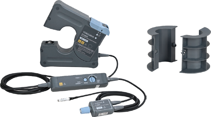
그림 1. 센서 외관(왼쪽) 및 도체 위치 조정기(오른쪽)
4.3 DL950의 실시간 연산 및 거듭제곱 연산
DL950의 실시간 연산 기능(/G03 옵션)은 캡처된 신호에 대해 다양한 계산을 수행하고 결과를 실시간 트랜드 그래프로 표시합니다. 이 기능을 사용하면 계산 결과에 대한 트리거를 설정하거나 자동 파형 파라미터 측정 및 커서 측정을 수행할 수 있습니다. 입력 신호와 계산 결과 모두에 필터를 적용할 수도 있습니다. 또한 실시간 연산 기능은 입력 채널과 독립적이므로 32개 입력 채널과 추가 16개 채널의 실시간 계산 결과를 동시에 표시하고 분석할 수 있습니다.
전력 연산 기능(/G05 옵션)은 실효값, 유효 전력, 적분 전력, 고조파를 포함하여 각 사이클에 대해 최대 126가지 유형의 전력 파라미터를 실시간으로 계산합니다. 측정 중인 전압 및 전류 신호와 계산된 전력 파라미터의 트랜드 파형을 실시간으로 동시에 표시합니다. 전력 파라미터의 트랜드 파형에 대한 트리거를 설정할 수도 있습니다.
*전력 연산 옵션에는 실시간 연산 옵션이 포함됩니다.
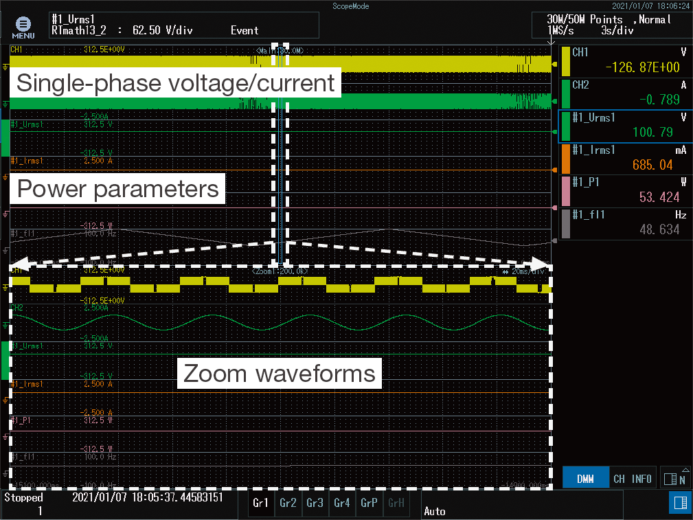
그림 2. 단상 전압/전류 파형 및 전력 파라미터 계산 예시
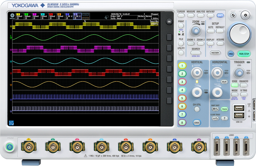
또한, 신호를 더욱 빠르게 측정해야 할 경우 DLM5000 혼합 신호 오실로스코프를 사용하여 3상 전압 및 대용량 전류의 파형을 측정할 수 있습니다.

1. Introduction
As a response to global environmental issues, wind power generation systems are being introduced in the renewable energy sector. These systems supply electricity to the grid by connecting the power generated by generator motors. Wind power generation is a mechanism that employs the force of the wind to rotate turbines, converting the rotational motion into electricity. This makes it possible to generate clean energy without consuming fossil fuels.
2. Challenges
Since the amount of renewable energy generated often fluctuates due to natural conditions, sudden increases in generation capacity can sometimes cause instability in the power grid. When this happens, waveform observation devices are needed for capturing fluctuations in large current waveforms and examining them in detail.
In addition, conducting tests that continuously monitor the grid over an extended period may be necessary to capture abnormal waveform data. However, long-term waveform monitoring generates a large amount of data, making it difficult to find noteworthy waveforms or abnormal data.

Solving this problem requires using waveform measuring instruments and sensors capable of measuring large currents to perform long-term waveform data measurements, check, and monitor abnormal data.
3. Solutions provided by DL950 and AC/DC split core current sensors
- Current accuracy (50/60 Hz): ±(0.2% of reading + 0.01% of range)
- User-friendly, high-precision current sensors that do not require cable removal
- Can measure large currents up to AC 1000 A/DC 1500 A*
*DC 1500 A (continuous operation) at the max. operating temperature plus 40°C - Carrier frequency measurement at a high bandwidth of 300 kHz (−3 dB)
- Accurate measurement in noisy environments due to outstanding Common Mode Rejection Ratio (CMRR) characteristics
- Real time waveform math and power math (DL950)
- Synchronized measurement with WT5000 based on IEEE1588 (DL950)
4. Waveform measurement with a large-current sensor
4.1 A high-accuracy AC/DC current sensor that is easy to connect to waveform measuring instruments for measurement
The CT1000S AC/DC split core current sensor can measure large currents up to AC 1000 A/DC 1500 A*, with current accuracy (50/60 Hz) of ±(0.2% of rdg + 0.01% of rng). Its open/close structure means you can measure large currents without having to remove the cables being measured.
Moreover, you can directly connect the current sensor not only to waveform measuring instruments but also to power meters, making it ideal for power measurement.
*DC 1500 A (continuous operation) at the max. operating temperature plus 40°C
4.2 Reduces the impact on the axial position of the cable being measured
The principle of a current sensor makes it ideal for the cable being measured to pass through the center of the sensor’s primary current hole. But in actual measuring situations passing the cable through the center of the hole is often difficult to do, and in any case the cable position affects the measurement values. This product uses a conductor position adjuster to restrict the axial position of the cable being checked, which reduces the impact of misalignment in the axial position when sensing the current with the AC/DC split core current sensor.

Figure 1. Sensor appearance (left) and conductor position adjuster (right)
4.3 Real time math and power math by the DL950
The DL950’s real time math function (/G03 option) performs various calculations on captured signals and displays the results in real time as trend graphs. This function enables you to set triggers on calculation results or perform automatic waveform parameter measurements as well as cursor measurements. You can also apply filters to both the input signals and calculation results. In addition, since the real time math function is independent of the input channels, real time calculation results for 32 input channels and additional 16 channels can be displayed and analyzed simultaneously.
The power math function (/G05 option) calculates up to 126 types of power parameters for each cycle in real time, including the RMS value, effective power, integrated power, and harmonics. It simultaneously displays both the voltage and current signals being measured, as well as the trend waveform of the computed power parameters in real time. You can also set triggers on trend waveforms for the power parameters.
*The power math option includes the real time math option.

Figure 2. Example of single-phase voltage/current waveforms and power parameter math
Moreover, when you need to measure signals even faster, you can measure the waveforms of three-phase voltages and currents of large currents using the DLM5000 Mixed Signal Oscilloscope.

하단영역

한국요꼬가와전기(주)
사업자등록번호 102-81-17301
경기도 용인시 기흥구 기흥로 58-1 기흥 ICT밸리 SK V1 A동 407호 ~ 411호 (우) 16976 (분당선 기흥역 2번 출구 500m)
T&M 영업본부 : 02-2628-3813
서비스팀 :02-2628-3872
팩스 : 02-2628-3899
COPYRIGHT ⓒ 2024 YOKOGAWA ELECTRIC CORPORATION. ALL RIGHTS RESERVED.