



요꼬가와는 1915년 창립이래 계측, 제어, 정보기술을 축으로
최첨단의 제품을 산업계에 제공함으로써 사회 발전에 공헌해오고 있습니다.
제품기초지식
전력을 측정하는 방법
제품이 전력을 사용하는 경우, 전력 소비량 및 전력 품질 측정은 제품 설계 및 테스트의 필수적인 부분이어야 합니다. 이러한 측정은 제품 설계를 최적화하고, 표준을 준수하며, 고객에게 제품 명판에 필요한 정보를 제공하는 데 필수적입니다. 하지만 전력을 어떻게 측정할까요?
이 글에서는 전력 측정의 기본 원리부터 시작하여 측정에 일반적으로 사용되는 계측기 및 관련 구성 요소에 이르기까지 전력 측정에 대한 최적의 방법을 다룹니다. 마지막으로, 앞서 설명한 내용을 실제 측정 문제에 적용하는 사례를 제시하며 마무리합니다.
우리 대부분은 기본적인 전력 측정 공식에 대해 접해봤겠지만, 이 정보를 요약하고 제품 설계 및 테스트에 어떻게 적용되는지 보여주는 입문서는 유용합니다.
전력 측정 기초
전류는 어떻게 측정하나요?
직류(DC) 전력 측정은 와트(W) = 볼트(V) × 암페어(A)라는 간단한 공식으로 나타낼 수 있어 비교적 간단합니다 . 교류(AC) 전력 측정의 경우, 역률(PF)이 고려되어 와트(W) = 볼트(V) × 암페어(A) × 역률(PF)이라는 공식이 성립하여 계산이 복잡해집니다. 이렇게 측정된 교류 전력은 유효 전력, 실효 전력 또는 피상 전력이라고 합니다. 교류 시스템에서 볼트(V) × 암페어(A)는 피상 전력이라고도 합니다.
전력 소비량은 최소 한 주기 동안의 전력 소비량을 계산하여 측정합니다. 디지털화 기술을 사용하여 순간 전압과 순간 전류를 곱한 후, 이를 특정 시간 동안 누적 및 적분하여 전류 값을 구합니다. 이 방법은 계측기의 대역폭까지 고조파 성분을 포함하여 정현파 또는 왜곡된 파형 등 모든 파형에 대해 실효 전력과 실효값(RMS)을 정확하게 측정할 수 있습니다.

단상 및 삼상 전력 측정
블론델 변환에 따르면 전체 전력은 시스템의 전선 수보다 하나 적은 전력계로 측정할 수 있습니다. 따라서 단상 2선식 시스템에는 전력계 1개, 단상 3선식 시스템에는 전력계 2개(그림 1 참조), 3상 3선식 시스템에는 전력계 2개, 그리고 3상 4선식 시스템에는 전력계 3개가 필요합니다.
전류를 측정하는 장치는 무엇입니까?
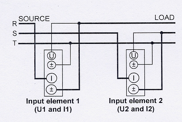 | 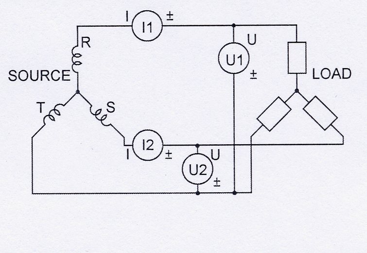 |
그림 1. 2와트미터 방식은 3P3W 시스템에 직접 연결하여 전력을 측정할 수 있습니다. Pt = P1 + P2
이 맥락에서 와트미터는 하나의 전류 입력과 하나의 전압 입력을 통해 전류를 측정하는 장치입니다. 많은 전력 분석기 및 배전반(DSO)은 와트를 측정할 수 있는 여러 개의 전류/전압 입력 쌍을 갖추고 있어, 사실상 하나의 장비 내에서 여러 개의 와트미터 역할을 합니다. 따라서 적절하게 사양이 지정된 하나의 전력 분석기로 3상 4선식 전력을 측정할 수 있습니다.
단상 2선식 시스템(그림 2)에서 와트미터로 감지되는 전압과 전류는 부하에서 소모되는 총 전력과 같습니다. 전압은 두 전선 사이에서 측정되고, 전류는 부하에 전력을 공급하는 전선(일반적으로 활선이라고 함)에서 측정됩니다. 전압은 일반적으로 전력 분석기로 최대 1000V RMS까지 직접 측정할 수 있습니다. 더 높은 전압을 측정하려면 AC 시스템에서 전압 변압기(VT)를 사용하여 전압을 장비에서 측정 가능한 수준으로 낮춰야 합니다. 전류는 장비에 따라 다르지만 일반적으로 전력 분석기로 최대 50A까지 직접 측정할 수 있습니다. 교류 시스템에서는 높은 전류를 처리하기 위해 전류변압기(CT)를 사용해야 합니다. CT에는 여러 종류가 있습니다. 일부는 회로에 직접 설치되고, 다른 일부는 전류가 흐르는 케이블이 통과하는 창이 있으며, 또 다른 종류는 클램프온 방식입니다. 직류 전류의 경우에는 일반적으로 션트가 사용됩니다. 션트는 회로에 설치되며, 계측기는 낮은 레벨의 밀리볼트 신호를 측정합니다.
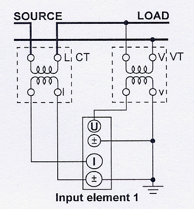
그림 2. 단상 2선식 시스템은 전류 변압기와 전압 변압기를 사용합니다.
단상 3선식 시스템(그림 3)에서 총 전력은 두 개의 전력계 측정값의 대수적 합입니다. 각 전력계는 활선 중 하나와 중성선에 연결되며, 각 활선에서 전류를 측정합니다. 총 전력은 Pt = P1 + P2로 계산됩니다.
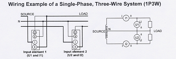
그림 3. 두 개의 전력계가 단상 3선식 시스템(1P3W)에 연결되어 있다.
3상 4선식 시스템(그림 4)에서 세 개의 전력계는 각각 활선과 중성선 사이의 전압을 측정하고, 세 개의 활선 중 하나의 전류를 측정합니다. 각 전력계는 3상 시스템의 단일 상을 측정하므로, 3상 전체 전력은 세 전력계 측정값의 대수적 합입니다. Pt = P1 + P2 + P3
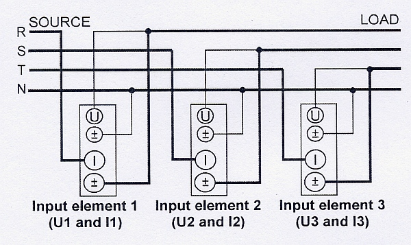 | 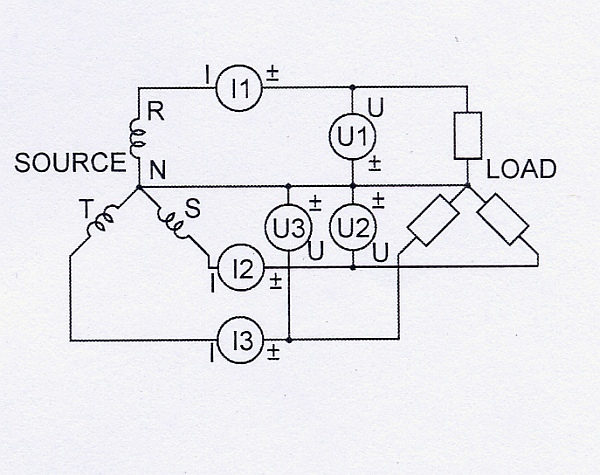 |
그림 4. 이 3상 4선식 시스템은 3개의 전력계를 사용합니다.
3상 3선식 시스템(그림 5)에서 두 개의 전력계는 세 개의 전선 중 임의의 두 전선에서 상 전류를 측정합니다. 각 전력계는 세 개의 전원 공급선 중 두 선 사이의 선간 전압을 측정합니다. 이 구성에서 총 전력(와트)은 두 전력계 값의 대수적 합으로 정확하게 측정됩니다. Pt = P1 + P2. 이는 시스템이 평형이든 불평형이든 관계없이 성립합니다.
부하가 불균형한 경우, 즉 상 전류가 서로 다른 경우, 총 전력은 정확하지만 총 무효 전력(VA)과 역률은 오차가 발생할 수 있습니다. 하지만 전력 분석기는 균형 또는 불균형 부하를 가진 3상 3선 시스템에서 정확한 측정을 보장하기 위해 특수한 3V3A 배선 구성을 사용할 수 있습니다. 이 방법은 세 개의 전력계를 사용하여 세 상 모두를 모니터링합니다. 첫 번째 전력계는 저항(R)상과 전위(T)상 사이의 전압을 측정하고, 두 번째 전력계는 안정(S)상과 전위(T)상 사이의 전압을 측정하며, 세 번째 전력계는 저항(R)상과 안정(S)상 사이의 전압을 측정합니다. 각 전력계는 상 전류를 측정합니다. 총 전력 계산에는 여전히 두 개의 전력계를 사용하는 방식이 적용됩니다. Pt = P1 + P2. 그러나 총 무효 전력(VA)은 (√3/3)(VA1 + VA2 + VA3)으로 계산됩니다. 불균형 부하에 대한 정확한 측정 및 계산을 위해 세 개의 전압과 전류가 모두 사용됩니다.
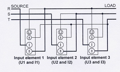 | 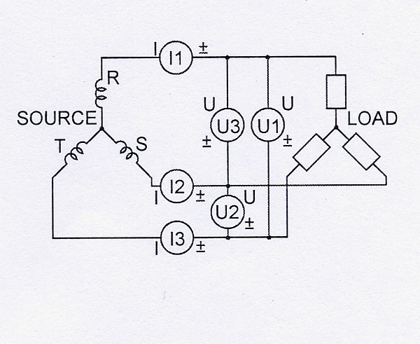 |
그림 5. 3상 3선식 시스템은 3개의 전력계를 사용하는 방식을 통해 불균형 부하에 대한 정확한 측정을 수행합니다.
역률 측정
역률은 종종 측정해야 하며 이 값은 가능한 한 1(1.0)에 가깝게 유지해야 합니다.
전력 시스템에서 역률이 낮은 부하는 동일한 유효 전력을 전달할 때 역률이 높은 부하보다 더 많은 전류를 소모합니다. 전류가 높을수록 배전 시스템에서 에너지 손실이 커지고 더 굵은 전선 및 기타 장비가 필요하게 됩니다. 이러한 대형 장비 비용과 에너지 손실 때문에 전력 회사는 일반적으로 역률이 낮은 산업 또는 상업 고객에게 더 높은 요금을 부과합니다.
그림 6은 전류가 전압보다 44.77° 뒤쳐져 역률이 0.70995인 경우를 보여줍니다. 피상 전력(S1)은 120.223 VA였습니다. 그러나 실제 전력(P1)은 85.352 W에 불과했습니다.
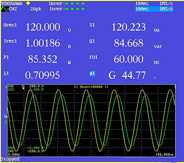
그림 6. 전력 분석기 화면은 전압과 전류 사이의 위상차를 보여줍니다.
전력을 소비하는 장치의 역률이 좋으면 전체 전력 시스템의 역률도 좋아지고, 반대로 역률이 낮으면 전체 시스템의 역률도 나빠집니다. 역률이 떨어지면 상당한 비용을 들여 역률 보정 장치를 사용해야 하는 경우가 많습니다. 이러한 장치는 대부분 커패시터인데
, 이는 대부분의 전력 소비 부하가 유도성이기 때문입니다. 인덕터에서는 전류가 전압보다 뒤쳐지는데, 이를 지연 역률이라고 합니다. 커패시터에서는 전류가 전압보다 앞서는데 , 이를 진상 역률이라고 합니다. 교류 모터는 유도성 부하의 예이고, 소형 형광등은 용량성 부하의 예입니다.
3상 4선식 시스템에서 전체 역률을 측정하려면 3개의 전력계가 필요합니다. 각 전력계는 와트를 측정하고, 전압과 전류도 측정합니다. 역률은 각 전력계에서 측정된 총 와트 수를 총 전압-전류로 나누어 계산합니다.
3상 3선식 시스템에서 부하가 불균형할 경우, 즉 각 상의 전류가 다를 경우, 역률은 2와트미터법 대신 3와트미터법을 사용하여 측정해야 합니다. 2와트미터법은 2암페어만 측정하기 때문에 세 번째 상의 전류 측정값에 차이가 생기면 측정값에 오차가 발생할 수 있습니다.
가정용 가전제품 전력 측정
전력 측정의 대표적인 응용 분야는 에너지 스타(Energy Star) 또는 IEC62301 표준을 기반으로 하는 가전제품의 대기 전력입니다. 두 표준 모두 필요한 전력 정확도, 해상도 및 고조파와 같은 기타 전력 측정 매개변수를 정의합니다. IEC62301 표준에는 다양한 기기에 대한 특정 테스트 매개변수를 정의하는 25개의 추가 표준이 있습니다. 예를 들어, IEC60436은 전기 식기세척기의 성능 측정 방법을 정의합니다.
대기 모드는 사용자가 끌 수 없고 무기한으로 지속될 수 있는 가장 낮은 전력 소비 모드로 정의되며, 기기가 주 전원에 연결되어 제조업체의 지침에 따라 사용될 때 유지됩니다. 대기 전력은 표준에 따라 측정했을 때 대기 모드에서의 평균 전력입니다.
대기 전력 또는 이와 유사한 응용 분야의 전력 소비를 측정하는 주요 방법은 세 가지입니다. 전력 값이 안정적인 경우 특정 시점의 순간 계측기 판독값을 사용할 수 있습니다. 전력 값이 안정적이지 않은 경우 시간 경과에 따른 계측기 판독값의 평균을 사용하거나 총 에너지 소비량을 측정합니다. 와트시(Wh)는 특정 기간 동안 측정한 후 해당 기간으로 나누어 구할 수 있습니다.
총 에너지 소비량을 측정하고 시간으로 나누는 방식은 안정적인 전력과 변동하는 전력 모두에서 가장 정확한 값을 제공하며, 당사의 전력 분석기를 사용할 때 일반적으로 사용되는 방법입니다. 하지만 총 에너지 소비량을 측정하려면 전력을 지속적으로 측정하고 합산해야 하므로 더욱 정교한 장비가 필요합니다.
전력 측정 도구
전력은 일반적으로 디지털 전력 분석기 또는 전력 분석 펌웨어가 탑재된 DSO(디지털 저장 오실로스코프)를 사용하여 측정합니다. 대부분의 최신 전력 분석기는 완전히 전자식이며, 아날로그 신호를 디지털 형태로 변환하기 위해 디지털 변환기를 사용합니다. 고급 분석기는 디지털 신호 처리 기술을 사용하여 값을 결정하는 데 필요한 계산을 수행합니다.
전력 분석용 DSO는 특수 펌웨어를 사용하여 정확한 전력 측정을 수행합니다. 그러나 디지털화된 파형에서 추출한 샘플 데이터에 의존하기 때문에 다소 제한적입니다. 전류 및 전압 프로브를 사용하기 때문에 절대적인 정확도가 필수적이지 않고 전력 주파수가 비교적 높은 보드 및 부품 레벨 작업에 적합합니다.
전력 분석기는 일반적으로 최대 1000V RMS 전압 레벨에서 최대 50A RMS까지 직접 측정할 수 있으므로 대부분의 테스트 대상 제품을 직접 연결할 수 있습니다. 반면, DSO는 전력 측정을 위해 전압 및 전류 프로브를 사용해야 합니다 . 변류기(CT)는 입력 전류와 출력 전류의 비율(예: 20:5)로 정격이 표시됩니다. CT의 다른 중요한 매개변수로는 정확도, 위상 편이, AC 전력 측정
주파수 범위 등이 있습니다 . VT(전압 변환기)는 실제 전압을 전력 측정 장비 에서 수용할 수 있는 수준으로 낮추는 데 사용됩니다 . 예를 들어, 테스트 대상 제품의 정격 전압이 480VAC이고 측정 장비의 최대 허용 전압이 120VAC인 경우 4:1 비율의 VT가 필요합니다. DSO(디지털 전압 센서)는 일반적으로 전력 분석기만큼 정확하지 않고 높은 전류 및 전압 입력을 직접 처리할 수 없지만, 적절한 프로브를 사용하면 최대 500MHz의 훨씬 높은 주파수에서 전력을 측정할 수 있습니다. 또한 DSO는 특정 응용 분야에서 전력 분석기보다 여러 가지 이점을 제공합니다. 예를 들어, 연결이 간편한 전용 프로브, 프로브 위상 보정, 최대 8개의 다중 채널 입력 등이 있습니다. DSO의 일반적인 응용 분야는 스위칭 전원 공급 장치용 회로 기판 설계와 같은 보드 레벨 측정입니다. DSO 또는 전력 분석기로 측정 및 분석하는 일반적인 매개변수에는 스위칭 전력 손실, 장치 전력 소비, 스위칭 잡음 레벨, 고조파, 출력 전력 및 출력 안정성 등이 있습니다.
DSO를 사용할 때는 차동 전압 프로브와 전류 프로브가 필요합니다(그림 7). 전류 프로브는 그림과 같이 주요 전류가 흐르는 전선 중 하나에 연결합니다. 종종 구성 요소의 전압은 접지를 기준으로 하지 않으므로 DSO 접지와 구성 요소 접지를 분리하기 위해 차동 전압 프로브가 필요합니다. 전력 분석기 또는 DSO와 필요에 따라 CT 및 PT 외에도 전력 측정을 위한 프로브, 클램프 및 전선과 같은 기타 보조 구성 요소가 필요합니다. 필요한 모든 계측기와 구성 요소가 준비되면 다음 단계는 정확히 어떤 계측기가 필요한지, 그리고 이러한 계측기를 부하에 어떻게 연결해야 하는지 확인하는 것입니다.
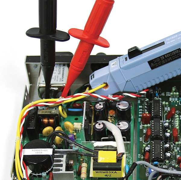
그림 7. 전압 프로브와 전류 프로브를 오실로스코프에 연결하여 전압과 전류를 측정합니다.
전력 분석기는 일반적으로 가전제품의 전력 측정이나 비교적 높은 전압, 낮은 주파수, 높은 정확도가 요구되는 기타 전력 측정에 적합한 장비입니다. 하지만 보드 레벨 측정에는 일반적으로 DSO(디지털 신호 증폭기)가 사용됩니다.
위에서 제시된 정보를 활용하면 다양한 전력 측정 용도에 맞는 적절한 장비와 도구를 선택하고 연결할 수 있습니다. 이러한 장비에서 수집된 정보는 설계 최적화, 표준 준수, 명판 정보 제공 등에 활용될 수 있습니다.
If a product uses power, then power consumption and power quality measurements must be a part of product design and test. These measurements are essential to optimize product design, comply with standards, and provide nameplate information to customers. But how do you measure electricity?
This article will discuss best practices to measure electrical power, starting with power measurement basics and proceeding to the types of instruments and associated components typically used to make measurements. The article will conclude with real-world examples, which apply the information imparted earlier in the article to solve practical measurement problems.
Although most of us have been exposed to basic power measurement equations, a primer is helpful to summarize this information and to show how it applies to product design and test.
Power Measurement Basics
How is electrical current measured?
DC power measurement is relatively simple as the equation is simply watts = volts x amps. For AC electrical power measurement, the power factor (PF) introduces complexity as watts = volts x amps x PF. This measurement of AC power is referred to as active power, true power, or real power. In AC systems, multiplying volts x amps = volt-amps, also called apparent power.
Power consumption is measured by calculating it over time, using at least one complete cycle. Using digitizing techniques, the instantaneous voltage is multiplied by the instantaneous current then accumulated and integrated over a specific time period to provide a measurement of electrical current. This method provides a true power measurement and true RMS measurements for any waveform, sine or distorted, including harmonic content up to the bandwidth of the instrument.

Single-phase and Three-phase Power Measurement of Electrical Power
The Blondel Transformation states that total power is measured with one less wattmeter than the number of wires in the system. Therefore, a single-phase, two-wire system will require one wattmeter, a single-phase, three-wire system will require two wattmeters (Figure 1), a three-phase, three-wire system will require two wattmeters, and a three-phase, four-wire system will require three watt meters.
What Device Measures Current?
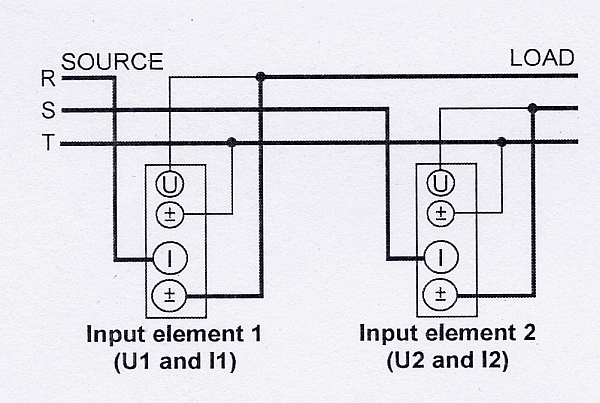 | 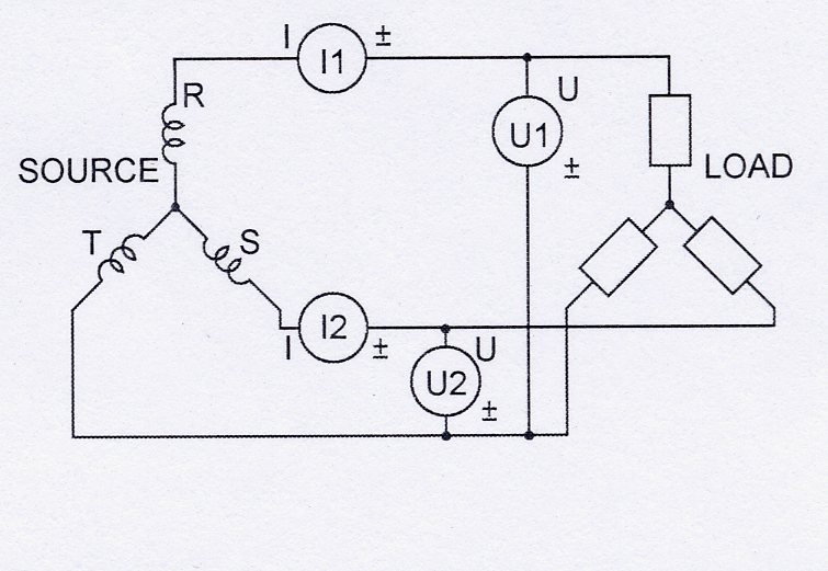 |
Figure 1. The two-wattmeter method can measure power through direct connections to a 3P3W system. Pt = P1 + P2
In this context, a wattmeter is a device used to measure current via one current and one voltage input. Many Power Analyzers and DSOs have multiple current/voltage input pairs capable of measuring watts, in effect acting as multiple wattmeters within a single instrument. Thus, it’s possible to measure three-phase 4-wire power with one correctly specified Power Analyzer.
With a single-phase, two-wire system (Figure 2), the voltage and current detected by the wattmeter are equal to the total power dissipated by the load. The voltage is measured between the two wires, and the current is measured in the wire supplying power to the load, often called the hot wire. Voltage can typically be measured directly by a Power Analyzer up to 1000 V RMS. Higher voltages will require the use of a VT (Voltage Transformer) on an AC system to step down the voltage to a level that can be measured by the instrument. Currents can typically be measured directly by a Power Analyzer up to 50 A, depending on the instrument. Higher currents will require the use of a CT (Current Transformer) on an AC system. There are different types of CTs. Some are placed directly in-line. Others have a window which the current-carrying cable passes through. The third kind is a clamp-on type. For DC currents, a shunt is typically used. The shunt is placed in line and a low level millivolt signal is measured by the instrument.
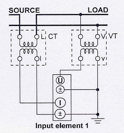
Figure 2. A single-phase, two-wire system uses a current transformer and voltage transformer.
With a single-phase, three-wire system (Figure 3), the total power is the algebraic sum of the two wattmeter readings. Each wattmeter is connected from one of the hot wires to the neutral, and current is measured in each hot wire. Total Power is calculated as Pt = P1 + P2.
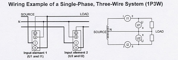
Figure 3. Two wattmeters connect to a single-phase, three-wire system (1P3W).
With a three-phase, four-wire system (Figure 4), the three wattmeters each measure voltage from a hot wire to the neutral, and each wattmeter measures current in one of three hot wires. The total power for the three phases is the algebraic sum of the three wattmeter measurements, as each meter is in essence measuring a single phase of the three-phase system. Pt = P1 + P2 + P3
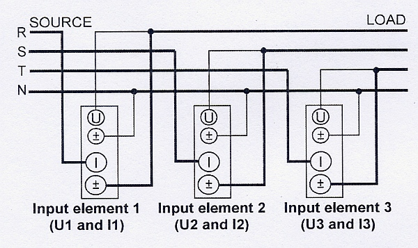 | 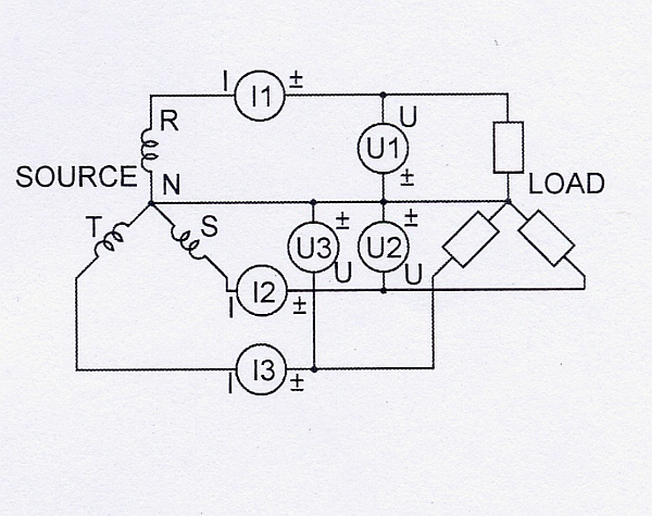 |
Figure 4. This three-phase, four-wires system uses three wattmeters.
With a three-phase, three-wires system (Figure 5), the two wattmeters measure phase current in any two of three wires. Each wattmeter measures a line-to-line voltage between two of the three power supply lines. In this configuration, the total power, watts is accurately measured by the algebraic sum of the two wattmeter values. Pt = P1 + P2. This holds true if the system is balanced or unbalanced.
If the load is unbalanced, meaning that the phase currents are different, total power will be correct, but the total VA and power factor could be in error. Power analyzers, though, may have a special 3V3A wiring configuration to ensure accurate measurements on three-phase, three-wire systems with a balanced or unbalanced load. This method uses three watt meters to monitor all three phases. One wattmeter measures voltage between the R and T phases, a second wattmeter measures voltage between the S and T phases and a third wattmeter measures voltage between the R and S phases. The phase currents are measured by each wattmeter. The two-wattmeter method is still used to calculate total power. Pt = P1 + P2. The total VA, however, is calculated as (√3/3)(VA1 + VA2 + VA3). All three voltages and currents are used to make accurate measurement and calculations on the unbalanced load.
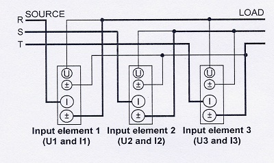 | 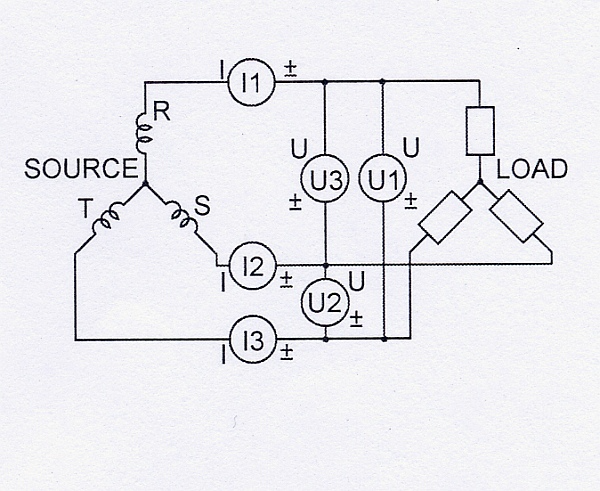 |
Figure 5. A three-phase, three-wire system uses the three-wattmeter method to achieve accurate measurements on an unbalanced load.
Power Factor Measurement
Power factor must often be measured, and this value should be kept as close as possible to unity (1.0).
In an electric power system, a load with a low power factor draws more current than a load with a high power factor for the same amount of useful power transferred. The higher currents increase the energy lost in the distribution system and require larger wires and other equipment. Because of the costs of larger equipment and wasted energy, electrical utilities will usually charge a higher cost to industrial or commercial customers exhibiting a low power factor.
Figure 6 shows current lagging voltage by 44.77°, which gave a power factor of 0.70995. The apparent power, S1, was 120.223 VA. The true power, or real power, P1, however, was only 85.352 W.
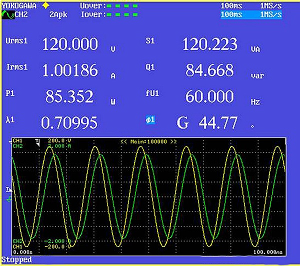
Figure 6. A power analyzer screen shows a phase difference between voltage and current.
If power-consuming devices have good power factors, then the entire power system will as well, and vice versa. When power factors drop, power-factor-correction devices must often be used, at considerable expense. These devices are typically capacitors because the bulk of most power-consumption loads are inductive.
The current lags the voltage in an inductor; this is known as a lagging power factor. The current leads the voltage in a capacitor; this is known as a leading power factor. An AC motor is an example of an inductive load, and a compact fluorescent lamp is an example of a capacitive load.
To determine total power factor on a three-phase 4-wire system, three wattmeters are required. Each meter measures watts, and measurements are also made of the volts and amps. The power factor is then calculated by dividing the total watts from each meter by the total volt-amps.
With a three-phase, three-wire system, power factor should be measured using the three wattmeter method instead of the two wattmeter method if the load is unbalanced, that is, if the phase currents are different. Because the two wattmeter method only makes two amp measurements, any differences in the amp reading on the third phase will cause inaccuracies.
Household Appliance Power Measurement
A typical application for power measurement is standby power for household appliances that are based on Energy Star or IEC62301 standards. Both standards define the required power accuracy, resolution and other power measurement parameters, such as harmonics. Within the IEC62301 standard, there are an additional 25 standards that define the specific test parameters for various appliances. For example, IEC60436 defines the methods for measuring the performance of electric dishwashers.
Standby mode is defined as the lowest power consumption mode that cannot be turned off by the user and that may persist for an indefinite time when an application is connected to the main electricity supply and used in accordance with the manufacturer’s instructions. Standby power is the average power in standby mode when measured in accordance with the standard.
There are three main methods to measure power consumption for standby power or other similar applications. If the power value is stable, then the instantaneous instrument reading at any point in time can be used. If the power value isn’t stable, then take either an average of the instrument readings over time or measure total energy consumption. Watt-hours can be measured over a specified period of time and then divided by that time.
Measuring total-energy consumption and dividing by time yields the most accurate values with both steady and fluctuating power and is the method commonly employed when using our Power Analyzers. But measuring total energy consumption requires a more sophisticated instrument because power must be continuously measured and totalized.
Tools for Power Measurement
Power is typically measured with a digital power analyzer or a DSO (digital storage oscilloscope) with power-analysis firmware. Most modern power analyzers are entirely electronic and use digitizers to convert analog signals to digital forms. Higher end analyzers use digital signal processing techniques to make the calculations required to determine values.
Power-analysis DSOs use special firmware to make true power measurements. They are, however, somewhat limited because they rely on sample data from digitized wave forms. Their current and voltage probes make them well suited for board and component level work where absolute accuracy isn’t a must and power frequency is relatively high.
Power analyzers can typically measure up to 50 A RMS directly at voltage levels up to 1000 V RMS, so most products under test can be directly connected. On the other hand, a DSO will require the use of voltage and current probes to make the power measurements.
CTs are rated by the ratio of input to output current, for example 20:5. Other important CT parameters are accuracy and phase shift and frequency range for AC power measurement. VTs are used to step down the actual voltage to a level that can be accommodated by the power measurement instrument. For example, if the product under test is rated at 480 VAC and the instrument is limited to 120 VAC, then a 4-to-1 VT is required.
A DSO typically doesn’t provide the accuracy of a Power Analyzer and can’t directly accept high current and voltage inputs, but it can measure power at much higher frequencies up to 500 MHz with the appropriate probes. It also provides other advantages over Power Analyzers in certain applications including dedicated probes for ease of connection, probe phase compensation and up to eight multiple channel inputs.
A typical application for a DSO would be any type of board-level measurement, such as when designing circuit boards for a switching power supply. Parameters that are typically measured and analyzed with a DSO or a power analyzer include, but aren’t limited to, switching power loss, device power consumption, switching noise level, harmonics, output power, and stability of output.
When using a DSO, the required equipment will include differential voltage probes and a current probe (Figure 7). The Current Probe is connected around one of the main current carrying wires as shown in the picture. Often the voltages of components are not referenced to a ground level. Therefore a Differential Voltage Probe is required to isolate the DSO ground from the component ground. In addition to a Power Analyzer or a DSO and CTs and PTs as needed, other ancillary components for making power measurements are probes, clamps and wires. Once all needed instruments and components are on hand, the next step is to ascertain exactly what instruments are needed, and how these instruments should be connected to the load.
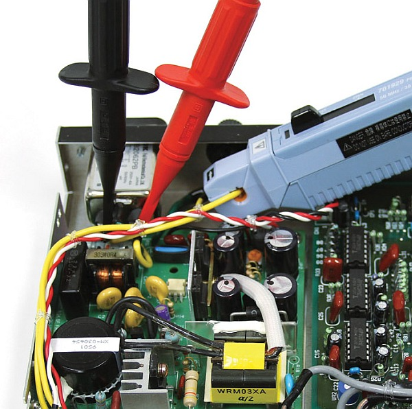
Figure 7. Use voltage probes and a current probe with an oscilloscope to measure voltage and current.
Power Analyzers are generally the instrument of choice for household appliance power measurements and other power measurements with relatively high voltage levels, low frequencies and high accuracy requirements. However, for board level measurements, a DSO is usually employed.
Using the information presented above, the selection and connection of the correct instruments and tools can be made for various power measurement applications. Information gathered from these instruments can then be used to optimize designs, comply with standards and provide nameplate information.
- 다음글
- 성공적인 고조파 측정 방법
하단영역

한국요꼬가와전기(주)
사업자등록번호 102-81-17301
경기도 용인시 기흥구 기흥로 58-1 기흥 ICT밸리 SK V1 A동 407호 ~ 411호 (우) 16976 (분당선 기흥역 2번 출구 500m)
T&M 영업본부 : 02-2628-3813
서비스팀 :02-2628-3872
팩스 : 02-2628-3899
COPYRIGHT ⓒ 2024 YOKOGAWA ELECTRIC CORPORATION. ALL RIGHTS RESERVED.